Next: Understanding Low-Voltage Switchgear: What It Is and Why It Matters


Understanding the Basics of LV Fuses
How LV Fuses Work – Operating Principle
In the complex landscape of electrical protection systems, low-voltage fuses remain one of the most reliable, cost-effective, and essential components for safeguarding equipment, personnel, and infrastructure. Whether you're specifying protection for an industrial distribution panel, designing a photovoltaic installation, or upgrading commercial switchgear, understanding LV fuses is fundamental to creating safe, compliant, and efficient electrical systems.
This comprehensive guide addresses the critical questions that electrical engineers, project managers, and procurement professionals face when selecting and implementing low-voltage fuse protection. From basic operating principles to advanced coordination strategies, we'll explore everything you need to make informed decisions about LV fuse deployment in modern electrical installations.
A low-voltage (LV) fuse is an overcurrent protection device specifically engineered to interrupt excessive current flow in electrical circuits operating at voltages up to approximately 1000 V AC or 1500 V DC. According to the latest IEC 60269-1:2024 standard, LV fuses are designed with rated breaking capacities of not less than 6 kA, making them suitable for protecting power-frequency AC circuits and DC circuits across residential, commercial, and industrial applications.
Unlike their circuit breaker counterparts, fuses provide current-limiting protection through a sacrificial element that physically melts when current exceeds safe operating levels. This fundamental difference gives fuses unique advantages in specific protection scenarios, particularly where extremely high short-circuit currents may occur.
Within the broader electrical protection hierarchy, LV fuses serve multiple critical functions:
Primary Protection: In many industrial and commercial installations, fuses act as the first line of defense against catastrophic short-circuit currents, protecting cables, transformers, and expensive equipment from damage.
Backup Protection: When coordinated properly with circuit breakers (MCBs, RCBOs, RCCBs), fuses provide secondary protection layers, ensuring that if primary devices fail to operate, the fuse will still interrupt dangerous fault conditions.
Cost-Effective Safety: Compared to sophisticated electronic protection relays or high-performance molded case circuit breakers (MCCBs), fuses deliver exceptional short-circuit interruption capability at a fraction of the cost, making them ideal for budget-conscious projects without compromising safety.
Semiconductor and Sensitive Equipment Protection: Specialized fuse types offer extremely fast-acting protection for sensitive electronic equipment, motor drives, and power electronic converters where even brief overcurrent exposure can cause permanent damage.
The debate between fuses and circuit breakers isn't about which is universally "better"—it's about selecting the optimal device for specific application requirements:
Fuses excel when:
Extremely high short-circuit breaking capacity is needed (up to 120 kA for NH fuses)
Space and budget constraints are significant
Current-limiting performance is critical to reduce let-through energy
Maintenance access is limited and long-term reliability is paramount
Protecting semiconductor devices or sensitive electronics
Circuit breakers (MCBs/RCBOs) excel when:
Frequent resetting capability is required
Precise adjustable trip characteristics are needed
Earth leakage protection must be integrated (RCBOs)
Visual indication of trip status is important
Remote control or monitoring is desired
Learn More: What is the difference between a fuse and a MCB?
Best Practice: Modern protection schemes often combine both technologies—using fuses for high-capacity main distribution and short-circuit protection, while deploying MCBs and RCBOs for branch circuits requiring frequent switching and nuanced protection characteristics.
Understanding fuse anatomy is essential for proper selection, installation, and maintenance. Each component plays a specific role in the fuse's protective function and operational characteristics.
The fuse element is the heart of the protection device—a precisely calibrated current-carrying conductor designed to generate controlled heat when current flows through it. Manufactured from materials like copper, silver, or alloys with specific melting points and temperature coefficients, the element's cross-sectional area and length determine its rated current capacity and time-current characteristics.
When overcurrent conditions occur, the element's temperature rises proportionally to I²R losses. Upon reaching its melting point, the element vaporizes, creating an arc that must be safely extinguished. Modern fuse elements incorporate notched or reduced cross-section areas that concentrate heat at specific points, ensuring predictable and rapid melting under fault conditions.
The fuse body provides critical functions beyond simple mechanical enclosure. Typically constructed from high-grade ceramic materials or specialized composite insulators, the housing must:
Electrically insulate the fuse element from surrounding conductors and structures
Mechanically contain the arc energy generated during interruption
Thermally manage heat dissipation during normal operation
Withstand pressure from arc plasma expansion during high-current interruption
Industrial NH fuses, for example, use robust ceramic bodies capable of containing arc pressures exceeding 100 bar, while smaller cartridge fuses may use glass-fiber reinforced polymer housings for lighter-duty applications.
Terminal design directly impacts installation ease, contact resistance, and long-term reliability. Common LV fuse terminal configurations include:
Blade Terminals (Knife-Style): Used primarily in NH fuses, these flat copper or brass blades slide into spring-loaded contacts in fuse bases, providing high current-carrying capacity and easy replacement without tools.
Cylindrical End-Caps: Standard in cartridge fuses, these metal caps make contact with spring-clip holders or screw terminals in distribution boards.
Bolted Connections: High-current fuse links often feature bolted terminal lugs for direct mounting to bus-bars, providing the lowest contact resistance for ratings above 400 A.
Spade or Ring Terminals: Some specialized fuses incorporate crimped or welded terminals for permanent installation in specific equipment.
Fuse links represent the serviceable component of many industrial fuse systems—the cartridge containing the fuse element that can be replaced after operation without changing the entire fuse assembly. This modular design offers significant advantages:
Reduced Replacement Cost: Only the link needs replacement, not the entire fuse holder or base
Inventory Simplification: Maintain stocks of fuse links rather than complete assemblies
Faster Service Restoration: Quick-change links minimize downtime during maintenance
Standardization: Common link sizes (NH00, NH1, NH2, NH3, NH4) ensure compatibility across manufacturers
Fuse holders secure the fuse or fuse link in position and provide electrical connections to the protected circuit. Industrial-grade holders offer several essential features:
Safety Interlocks: Many NH fuse holders incorporate mechanical interlocks that prevent removal under load, protecting maintenance personnel from arc flash hazards.
Indication Systems: Built-in mechanical indicators or provision for remote indication microswitches allow quick visual or remote identification of operated fuses in large distribution systems.
Mounting Options: DIN rail mounting for compact panels, back-plate mounting for distribution boards, or front-of-panel mounting for accessible service points.
Environmental Protection: Enclosed holders with IP ratings (IP20 to IP65) protect against dust, moisture, and accidental contact in demanding environments.
The LV fuse family encompasses diverse types optimized for specific applications, voltage ranges, and protection requirements. Understanding these categories enables precise specification matching.
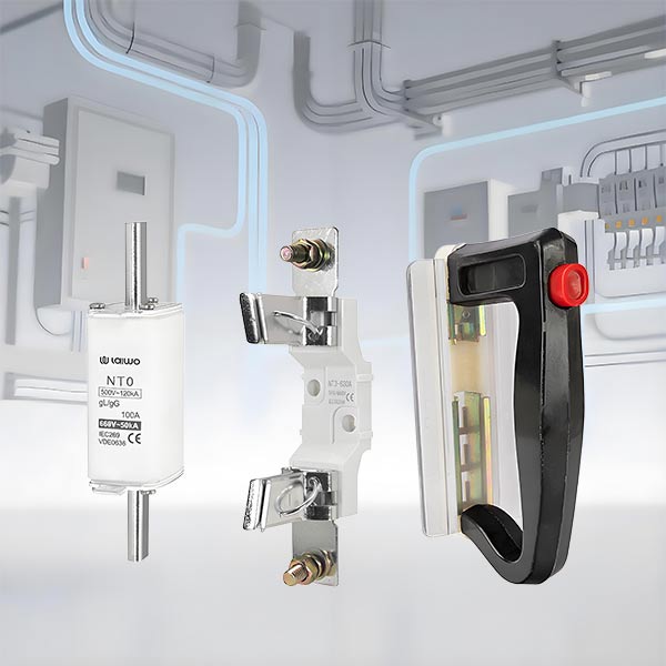
NH fuses represent the workhorse of industrial electrical distribution, named for their characteristic "Niederspannungs-Hochleistungs" (low-voltage high-capacity) German standard design. These robust devices dominate commercial and industrial installations worldwide.
Key Characteristics:
Current Ratings: 2 A to 1250 A, covering virtually all industrial distribution requirements
Breaking Capacity: Typically 120 kA at 500-690 V AC, with some variants rated to 80 kA
Size Designations: NH00, NH000, NH1, NH2, NH3, and NH4—each size corresponding to specific current ranges and physical dimensions
Utilization Categories: gG (general purpose/full-range breaking), gL (cable/line protection), aM (motor protection)
Applications: Motor control centers, industrial distribution boards, transformer primary protection, feeder circuits, and main distribution switchgear. NH fuses provide cost-effective protection in harsh environments where high breaking capacity is essential.
Selection Tip: Choose NH fuse size based on both current rating and available fault current—larger physical sizes offer higher energy dissipation capability even at the same current rating.
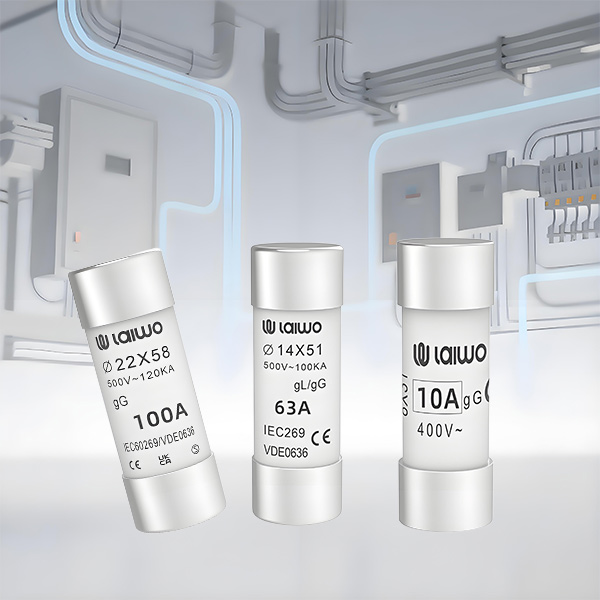
Cylindrical cartridge fuses are perhaps the most universally recognized fuse type, standardized internationally under various specifications including IEC 60269-2, UL 248, and BS 1362. Available in numerous sizes (10x38mm, 14x51mm, 22x58mm being common), these fuses suit a wide range of applications.
Common Types:
gG/gL Fuses: General-purpose and cable protection
aM Fuses: Motor starter and motor circuit protection
Photovoltaic Fuses (gPV): Specialized for DC PV applications
Applications: Distribution boards, motor starters, small industrial equipment protection, commercial switchgear, and control panel protection. Their compact size and standardized dimensions make them ideal for space-constrained applications.
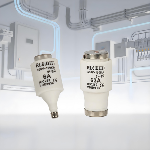
Bottle fuses feature threaded bases similar to incandescent light bulbs, screwing into compatible fuse holders. While less common in new installations, they remain prevalent in older industrial equipment, specialized machinery, and retrofit applications.
These fuses typically serve lower-current applications (up to 63 A) and offer simple replacement without tools. However, their susceptibility to incorrect rating substitution (users might install higher-rated fuses to prevent "nuisance tripping") makes them less favored in safety-critical modern installations.
The explosive growth of solar photovoltaic installations has driven development of specialized DC fuses designed for the unique challenges of direct-current fault interruption and the harsh environmental conditions of PV systems.
Critical Specifications:
Voltage Rating: Up to 1500 V DC (some emerging designs rated to 2000 V DC)
Current Ratings: Typically 1 A to 63 A for string protection; 100 A to 630 A for central inverter protection
Utilization Category: gPV (specifically designed and tested for photovoltaic applications)
Standards Compliance: IEC 60269-6 and UL 2579
Unique Requirements: Unlike AC fuses that benefit from natural current zero-crossings twice per cycle, DC fuses must forcefully extinguish the arc without this assistance. This requires specialized internal construction, arc-quenching materials, and significantly different time-current characteristics.
Applications: String combiner boxes, central inverter DC input protection, battery storage system DC bus protection, and DC distribution in electric vehicle charging stations.
Critical Selection Factor: Never substitute standard AC-rated fuses in DC applications above 100 V DC—the arc extinction mechanisms are fundamentally different, and catastrophic failure may result.
Understanding fuse operating principles enables engineers to predict protection behavior, coordinate devices effectively, and diagnose system performance.
Fuse operation follows a straightforward yet precisely engineered physical process:
1. Normal Operation: During normal current flow below the fuse's rated current (In), the fuse element carries current continuously while dissipating minimal heat. The element temperature stabilizes at a safe level determined by ambient conditions and mounting configuration.
2. Overload Condition: When current exceeds the rated value but remains below short-circuit levels (typically 1.1 to 10 times In), the element temperature rises according to I²t (current-squared-time) heating. The fuse element melts after a time interval inversely proportional to current magnitude—high overloads cause rapid melting, while slight overloads may take minutes or hours.
3. Short-Circuit Interruption: Under fault currents (typically >10 times In), the fuse element melts extremely rapidly—often within milliseconds—before fault current reaches its prospective peak value. This current-limiting action is a unique fuse characteristic: by opening the circuit before peak current is reached, fuses dramatically reduce mechanical stresses and thermal energy delivered to protected equipment.
4. Arc Extinction: After element melting, an arc forms across the gap. Internal arc-quenching materials (silica sand in high-capacity fuses, ceramic powder in others) absorb arc energy and promote rapid deionization. The fuse voltage drop increases dramatically during arcing, further limiting current flow until complete extinction occurs.
Every fuse type possesses a unique time-current characteristic curve that defines its protection profile. These curves, typically plotted on log-log scales, illustrate the relationship between overcurrent magnitude and operating time.
Pre-arcing Time (Melting Time): The interval from overcurrent initiation until element melting begins. This determines how quickly the fuse responds to various fault magnitudes.
Arcing Time: The brief period (typically 5-25 milliseconds) required for arc extinction after element melting. During this interval, the fuse still conducts current while its internal voltage drop rises.
Total Operating Time: Pre-arcing time plus arcing time represents the complete interval that overcurrent flows before interruption—critical for coordination calculations.
I²t Let-Through Energy: The total thermal energy (measured in ampere-squared-seconds) that passes through the fuse during operation. This parameter determines the thermal stress imposed on protected equipment and cables.
Professional electrical installations rarely rely on a single protection device. Instead, they implement coordinated protection schemes where upstream devices provide backup for downstream devices while ensuring only the device nearest the fault operates.
Fuse-to-Fuse Discrimination: When two fuses protect circuits in series, proper coordination ensures the downstream fuse operates for faults in its zone, while the upstream fuse only operates for faults between them or for downstream fuse failure. This requires careful selection based on I²t values and time-current curve separation.
Fuse-MCB Coordination: Combining fuses (typically upstream) with MCBs (downstream) leverages each device's strengths. The MCB provides convenient resetting for moderate overloads and branch circuit protection, while the fuse delivers high-capacity short-circuit backup protection. Coordination tables from manufacturers specify compatible combinations ensuring proper selectivity.
Fuse-RCBO Integration: In installations requiring both overcurrent and earth leakage protection, RCBOs (combined MCB + residual current device) handle branch circuits while upstream fuses provide short-circuit backup. This layered approach optimizes both safety and convenience.
Best Practice: Always verify coordination using manufacturer-supplied selectivity tables or perform detailed time-current curve analysis. Assumptions about coordination without verification can lead to incorrect tripping sequences, causing unnecessary disruption or leaving faults unprotected.
Strategic protection device selection requires understanding how fuses compare with alternative technologies across multiple dimensions: technical performance, operational characteristics, economics, and maintenance requirements.
This fundamental comparison shapes protection philosophy in virtually every electrical installation:
Fuses Advantages:
Breaking Capacity: Fuses routinely achieve 120 kA breaking capacity, far exceeding most MCBs (typically 6-25 kA)
Current-Limiting Performance: Inherent current limitation reduces let-through energy by 50-90% compared to non-current-limiting breakers
Cost-Effectiveness: Initial and lifecycle costs favor fuses for high-capacity applications
Reliability: No mechanical moving parts means fewer failure modes
Space Efficiency: Fuses occupy less panel space for equivalent protection ratings
No Periodic Testing Required: Unlike breakers requiring regular mechanical operation verification
MCBs Advantages:
Resettable Operation: No replacement parts needed after operation (major convenience advantage)
Visual Trip Indication: Easy identification of operated devices
Adjustable Protection: Some MCB types offer adjustable trip thresholds
Manual Switching: Can serve as both protection and isolation device
No Arc Flash During Replacement: Eliminated since no replacement is needed
Application Guidance:
Use fuses for: High fault-current locations, primary distribution, transformer protection, semiconductor protection, and applications requiring maximum breaking capacity
Use MCBs for: Branch circuits, lighting circuits, locations requiring frequent switching, and applications where resettability outweighs cost considerations
Use coordinated fuse-MCB combinations for: Optimal protection with fuses upstream (high-capacity backup) and MCBs downstream (convenient branch protection)
Learn More:
MCBs Guide: Types, Functions & Electrical Safety Tips
This comparison addresses different protection domains—overcurrent versus earth leakage:
RCCBs (Residual Current Circuit Breakers) detect earth leakage current (typically 30mA for personnel protection, 100-300mA for equipment protection) and trip to prevent electric shock hazards. However, RCCBs provide no overcurrent protection—they ignore overloads and short-circuits.
RCBOs (Residual Current Breaker with Overcurrent Protection) combine MCB overcurrent protection with RCCB earth leakage protection in a single device, offering comprehensive protection.
Fuses provide excellent overcurrent and short-circuit protection but offer no earth leakage protection—a critical limitation in circuits where shock hazards exist.
Optimal Solutions:
Fuse + RCCB: Use upstream fuses for short-circuit protection combined with RCCBs for earth leakage protection—provides complete protection at lower cost than all-RCBO solutions
Fuse + RCBO Downstream: Use fuses for main distribution with RCBOs for final circuits requiring both overcurrent and leakage protection
All-RCBO Approach: In installations prioritizing convenience and where space allows, RCBOs on all circuits provide comprehensive protection with maximum flexibility—though at higher initial cost
Critical Understanding: Fuses and earth leakage devices protect against different hazards. Complete protection requires addressing both overcurrent (via fuses or MCBs) and earth leakage (via RCCBs or RCBOs).
Learn More:
For higher-current applications (typically >125 A), the comparison shifts to fuses versus MCCBs:
MCCBs offer adjustable trip settings, high breaking capacities (up to 200 kA for premium models), and electronic trip units with advanced protection functions. However, they command premium prices—often 5-10 times the cost of equivalent fuse protection.
NH Fuses in larger sizes (NH3, NH4) provide comparable or superior breaking capacity at a fraction of the cost, though without adjustability or remote indication.
Economic Decision Point: For applications not requiring adjustability or frequent switching (main service entrances, transformer primaries, tie feeders), NH fuses deliver superior value. Where adjustment, metering, or remote control justify the investment, MCCBs become attractive despite higher costs.
Understanding real-world applications helps engineers recognize opportunities for optimal fuse deployment and avoid common specification errors.
Industrial motor control centers (MCCs) represent perhaps the most common NH fuse application. These panels distribute power to motors, drives, and machinery across manufacturing facilities, processing plants, and industrial campuses.
Typical Configuration:
Main Incoming Protection: NH3 or NH4 fuses (400-1250 A) protecting the incoming feeder
Feeder Protection: NH1 or NH2 fuses (50-400 A) protecting feeders to subsidiary panels or large equipment
Motor Branch Protection: NH00 or NH1 fuses with contactors for individual motor circuits
Auxiliary Circuits: Smaller cartridge fuses for control circuits, instrumentation, and auxiliary power
Why Fuses Excel Here: High available fault currents at industrial service entrances (often 50-100 kA) demand the breaking capacity and current-limiting performance that fuses deliver cost-effectively. The relatively infrequent operation of main distribution protection makes fuse replacement a minor consideration versus initial cost savings.
Photovoltaic installations from residential rooftop arrays to utility-scale solar farms rely heavily on specialized DC fuses for string and array protection.
String-Level Protection: Individual PV strings (series-connected panels) connect through string fuses (typically 10x85mm or 14x51mm gPV fuses, 1-20 A) in combiner boxes. These fuses protect against reverse current when panel failures or shading create abnormal current flows.
Array Combiner Protection: Combined string outputs pass through larger array protection fuses (typically NH-size gPV fuses, 32-400 A) before reaching central inverters. These fuses must interrupt DC fault currents while withstanding continuous exposure to harsh outdoor conditions.
Inverter Input Protection: Many inverter manufacturers specify DC fuses as required safety devices for warranty coverage, protecting the expensive inverter electronics from string-level faults.
Battery DC Bus Protection: Energy storage systems pair solar arrays with battery banks, requiring additional DC fuse protection on battery circuits where fault currents can be exceptionally high and sustained.
Critical Specification: Always specify fuses marked "gPV" or specifically rated for photovoltaic applications with appropriate DC voltage ratings (1000 V or 1500 V DC). Standard AC fuses are unsafe in DC PV applications.
Utility-scale and commercial battery energy storage installations present unique protection challenges—very low system impedance yields extremely high prospective fault currents, while DC architecture eliminates natural current zeros.
DC Fuse Applications:
Battery Rack Protection: Each battery string (series-connected modules) requires individual fuse protection
Bus Tie Protection: Fuses protect parallel connections between battery racks
DC Contactor Backup: Fuses provide backup protection for electronic switching devices
Short-Circuit Limitation: The current-limiting characteristics of properly selected fuses reduce mechanical stress on battery interconnects during fault events
AC Fuse Applications:
Inverter AC Output: NH fuses protect the AC connections between battery inverters and site distribution
Grid Interconnect: Main AC fuses provide short-circuit protection at the utility point of common coupling
Emerging Challenge: As battery systems scale toward multi-megawatt capacities with prospective fault currents exceeding 100 kA DC, fuse technology continues advancing to meet these extreme requirements.
Commercial and residential distribution boards traditionally used cartridge fuses extensively, though many modern installations favor MCB/RCBO combinations. However, fuses remain common and advantageous in specific scenarios:
Residential Service Entrances: Main service entrance fuses protect the meter-to-panel feeder, providing high breaking capacity backup protection for downstream MCB panels.
Commercial Tenant Panels: Where building owners maintain responsibility for tenant panel repairs, fuse protection eliminates tenant tampering with breaker settings while ensuring reliable protection.
EV Charging Distribution: Electric vehicle charging installations with multiple high-power charge points benefit from fuse protection of distribution circuits, with convenient RCBO protection at individual charge points.
Specialized Equipment Circuits: Building services equipment (HVAC, elevators, fire pumps) often specify fuse protection due to manufacturer requirements or electrical code mandates for specific equipment types.
When engineers, project managers, and procurement professionals evaluate LV fuse solutions, several factors drive decision-making beyond simple technical compliance:
NH fuses deliver breaking capacities to 120 kA—exceeding nearly all MCBs and rivaling only the most expensive MCCBs. This enables confident protection even in high-fault-current installations without costly upgrades to downstream equipment ratings.
Current-limiting performance reduces peak let-through current by 50-90%, translating directly to reduced mechanical stress on equipment, smaller required component ratings, and extended equipment lifespans.
Fewer failure modes mean higher reliability—fuses contain no mechanical trip mechanisms, calibrated springs, or electronic components to drift, fail, or require periodic testing. Once installed, properly rated fuses provide decades of reliable service without maintenance.
Straightforward selection based on circuit current, prospective fault current, and application category (gG, gL, aM, gPV) simplifies specification compared to breakers with multiple trip curve options, adjustable settings, and breaking capacity variations.
Lower initial costs particularly for higher current ratings and breaking capacities represent immediate project savings. An NH3 fuse-switch combination typically costs 30-50% less than an equivalent MCCB for the same current and breaking capacity.
Reduced installation time due to simpler mounting and connection requirements lowers labor costs.
Minimal maintenance requirements eliminate periodic testing costs associated with circuit breakers.
Predictable replacement costs allow accurate lifecycle budgeting—while fuses require replacement after operation, the replacement cost is known, unlike breaker repair costs which may vary widely.
Coordinated protection schemes leveraging fuses upstream with MCBs/RCBOs downstream optimize both protection performance and economics:
Capture cost savings where fuses excel (main distribution, high breaking capacity locations)
Preserve convenience where breakers excel (branch circuits, accessible locations)
Achieve proper discrimination without complex calculations or expensive electronic relays
Effective LV fuse specification requires systematic evaluation across multiple dimensions—understanding this framework enables confident decision-making:
LV fuses serve as current-limiting, overcurrent protection devices for circuits up to 1000 V AC or 1500 V DC, offering exceptional breaking capacity (6-120 kA) at cost-effective price points. Available in diverse types—NH (industrial knife-style), cartridge, bottle, and specialized DC/PV variants—each category targets specific application requirements.
Fundamental operating principles rely on controlled element melting proportional to I²t heating, followed by arc extinction in specialized quenching media. This physical process delivers inherent current limitation and exceptionally reliable protection without complex mechanisms.
Modern electrical installations rarely rely on single-tier protection. Instead, coordinated protection schemes leverage different device types at different distribution levels:
Upstream Fuses (Primary Protection): NH fuses at main distribution points provide high breaking capacity and current limitation for severe short-circuit protection.
Downstream MCBs (Secondary Protection): Branch circuit MCBs offer convenient resetting, manual switching capability, and cost-effective protection for final circuits where fault currents are more moderate.
RCBO Integration (Earth Leakage Protection): Where shock hazards exist, RCBOs add earth leakage protection to overcurrent protection—either throughout the installation or specifically for circuits with elevated risk (outdoor equipment, wet locations, portable equipment).
Verification Essential: Always verify coordination using manufacturer selectivity tables or detailed time-current curve analysis. Never assume devices will coordinate without confirmation.
Step 1: Define Circuit Parameters
Continuous current (calculate actual load current, apply derating factors for ambient temperature)
Prospective fault current at installation point
Circuit voltage (AC or DC)
Application type (motor, cable protection, semiconductor protection, etc.)
Step 2: Select Fuse Type
High current (>125 A) industrial: NH fuses
Moderate current (<125 A) standard protection: Cartridge fuses
DC photovoltaic: gPV-rated DC fuses at appropriate voltage rating
Battery systems: High-breaking-capacity DC fuses
Existing bottle-base installations: Equivalent bottle fuses
Step 3: Determine Ratings
Current rating: Select fuse rated 10-25% above continuous circuit current (higher margins for motor circuits subject to inrush)
Voltage rating: Must equal or exceed circuit voltage (can be higher, never lower)
Breaking capacity: Must equal or exceed prospective fault current at installation location
Step 4: Specify Utilization Category
gG (general purpose) for mixed loads and equipment protection
gL for cable and line protection where overload capacity advantage is useful
aM for motor circuits requiring high short-circuit capacity with limited overload protection
gPV for all photovoltaic DC applications
Step 5: Verify Coordination
Check manufacturer coordination tables for upstream-downstream device pairs
Ensure discrimination ratios (typically 1.6:1 for fuse-to-fuse, per coordination tables for fuse-MCB)
Verify let-through energy compatibility with downstream equipment ratings
LV fuses are single-use overcurrent protection devices that interrupt fault current through physical element melting and arc extinction. After operation, the fuse element must be replaced. They offer extremely high breaking capacities (up to 120 kA), inherent current limitation, and simple reliability with no moving parts.
Circuit breakers (MCBs, MCCBs) are resettable protective devices using mechanical or magnetic trip mechanisms that can be reset after operation without component replacement. They typically have lower breaking capacities than fuses (6-25 kA for MCBs, up to 200 kA for premium MCCBs), offer convenient manual switching and visible trip indication, but involve higher initial costs and more complex mechanisms.
Best choice depends on priorities: Fuses excel for maximum breaking capacity, current limitation, and lowest cost. Breakers excel for convenience, resettability, and applications requiring frequent manual switching.
Follow this systematic selection process:
1. Calculate actual load current including any continuous loads that must be derated per electrical codes (typically 125% factor).
2. Determine prospective fault current at the installation point—your electrical design calculations or utility fault current data provide this.
3. Select fuse current rating 10-25% above calculated load current. For motor circuits, account for locked-rotor current and starting duration.
4. Verify breaking capacity equals or exceeds prospective fault current. If fault current data is unavailable, select the highest practical breaking capacity as safety margin.
5. Match voltage rating to circuit voltage (fuse voltage must equal or exceed circuit voltage).
6. Specify utilization category: gG for general distribution, gL for pure cable protection, aM for motor feeders.
7. Confirm coordination with upstream and downstream devices using manufacturer tables.
DC arc extinction fundamentals differ critically from AC: Alternating current naturally passes through zero voltage/current twice per cycle (every 8.3ms at 60 Hz), facilitating arc extinction. Direct current maintains constant voltage and current, preventing natural arc extinction.
Standard AC fuses lack adequate DC arc-quenching capability. The internal construction, arc-chute geometry, and quenching media in AC fuses are optimized for AC interruption. When subjected to sustained DC arcs, AC fuses may fail to extinguish the arc, potentially leading to enclosure melting, fire, or sustained arcing faults.
gPV-rated fuses incorporate specialized design elements specifically for DC PV applications:
Enhanced arc-quenching media optimized for DC arc extinction
Extended arc-chute lengths providing greater arc voltage drop to force current to zero
Thermal cycling resistance for daily temperature swings in outdoor installations
UV-resistant materials for long-term outdoor exposure
Testing verification per IEC 60269-6 at actual DC voltages (1000 V or 1500 V DC)
Safety and warranty considerations: Many inverter manufacturers void warranties if proper gPV fuses aren't installed. Insurance companies may deny claims for fires caused by improperly rated fuses. Electrical inspectors increasingly reject installations using AC fuses for DC protection.
No—NH fuses and cartridge fuses are not interchangeable for several critical reasons:
Physical incompatibility: NH fuses use knife-blade terminals designed for NH fuse holders, while cartridge fuses use cylindrical end-caps requiring entirely different holder designs. They cannot physically mate with each other's holders.
Current rating mismatch: NH fuses span much higher current ratings (2-1250 A) than standard cartridge fuses (typically limited to 100-125 A maximum), meaning a cartridge fuse physically cannot safely carry the current an NH fuse circuit may require.
Breaking capacity differences: NH fuses typically offer 80-120 kA breaking capacity, while many cartridge fuses provide lower breaking capacity (20-50 kA depending on type). Substituting a lower-capacity device in a high-fault-current location creates severe safety hazards.
Voltage rating variations: Some cartridge fuses are rated only to 500 V AC while many NH installations operate at 690 V AC systems common in European industrial installations.
Proper approach: If replacement of NH fuse protection with cartridge fuse protection is necessary (perhaps to reduce physical size or cost), the entire fuse holder must be changed along with verification that:
The cartridge fuse current rating matches circuit requirements
Breaking capacity equals or exceeds prospective fault current
Voltage rating is appropriate
Physical space accommodates the alternative holder design
Coordination with upstream/downstream devices remains valid