
When specifying protection for an EV charger circuit, it’s critical to recognise that unlike typical domestic loads (lights, sockets, heating elements) the circuit for a dedicated EV charger behaves as a continuous, high-current, and sometimes fluctuating load. For example, a 7 kW single-phase charger will draw around 32 A continuously for the duration of the charge session. That contrasts with typical intermittent loads.
Because of that continuous duty:
The circuit must be capable of sustained operation without nuisance tripping due to overload or thermal stress.
Voltage drop and cable losses become more critical (the cable and breaker rating must support the higher current without excessive heating).
A dedicated circuit (breaker + cable) is required — sharing circuits risks voltage drop, over-loading, interference, and nuisance tripping.
The dynamic nature of the load also means the upstream distribution, cable impedance, and fault loop need specific scrutiny (for example when multiple chargers are installed).
The switching behaviour (inrush or soft start, depending on charger design) may differ from conventional loads and influences breaker curve selection.
Learn More:
Essential Electrical Protection for EV Charging Stations
What Size Circuit Breaker Do You Need for an EV Charger?
EV Charger Distribution Box vs Standard Distribution Box: What's the Difference?
Protection for EV charger circuits is not just a matter of “take a 32 A MCB and go”. There are several safety and regulatory concerns:
The relevant installation standard in the UK, Section 722 of BS 7671, sets out specific requirements for EV charging installations (e.g., dedicated circuit, RCD protection) beyond general wiring regulation.
The charging equipment standard (IEC 61851 series) applies: it addresses the fixed installation of EV conductive charging systems. In turn, that standard drives what the installation must provide.
Risks unique to EV circuits include:
Leakage/Residual current (including DC residual current): EV chargers and vehicles’ electronics may produce DC components that can blind conventional RCDs. For example, if a charger does not have a built-in RDC-DD (Residual Direct Current Detecting Device), then an RCD of Type B may be required.
Thermal stress: Because the load is continuous (often for multiple hours), the thermal rating of the breaker, its neighbouring devices, the consumer unit enclosure and adjacent cables must account for this continual load. For example, manufacturers recommend derating or choosing higher current devices when adjacent to other continuously-loaded circuits.
Earthing/fault loop issues: The earthing arrangement (TN-C-S / PME, TT or TN-S) may impose additional protective device requirements (e.g., open PEN detection) as set out in BS 7671 Regulation 722.411.4.1.
Because of the above, engineers and contractors must ensure that the protective devices chosen are not simply the standard MCB or RCD used for lighting or socket circuits — they must be appropriate for EV-charging duty and compliant with the regulatory framework.
Learn More:
From a B2B procurement/engineering perspective, there are several common pain points when specifying breakers/protection for EV charger circuits:
Compatibility: Ensuring the protective device type (MCB curve, RCD type) is compatible with the charger manufacturer’s specification and with the upstream distribution board layout (adjacent devices, consumer unit load, temperature rise). Mis-selection may lead to nuisance trips or non-compliance.
Maintenance / Testing: EV circuits must be installed with devices that allow for periodic testing (RCD test button, breaker trip characteristics, verification of thermal loading). If the installation is poorly documented or serviced, future testing may reveal non-compliance.
Future-proofing: Many installations now contemplate expansion (dual chargers, smart load management, grid-interaction). The breaker/distribution board selection needs to allow space for expansion, spare ways, load-sharing or dynamic balancing. Poor planning results in rewiring or consumer-unit upgrade later.
Supply chain / certification: When sourcing breakers/RCDs/RCBOs, distributors must ensure certification (BS EN 61008, 61009 for RCDs; manufacturer’s documentation for EVSE), UKCA/CE marking, and compatibility with the charger’s built-in protections (e.g., does the charger include an RDC-DD?). If the charger assumes built-in DC protection but the installed RCD cannot cope with DC residual current, that is a risk.
Thermal/adjacent load derating: As shown in surveys and commentary, the protective device might need to be overspecified (for example a 7 kW charger circuit may require a 63 A protective device under certain conditions) if other adjacent circuits are also continuous loads. Engineers must recognise this early to avoid undersizing.
Coordination with smart/load-management: In multi-charger installations (commercial or multi-residential), the breaker sizing and selection must align with the load-management strategy (e.g., if using dynamic load-balancing, the breaker must still be sized for worst-case demand). Failing to align these can lead to over-loading or unnecessary device upgrades later.
Learn More:
From Charger to Car: Complete Protection with Our EV Consumer Units
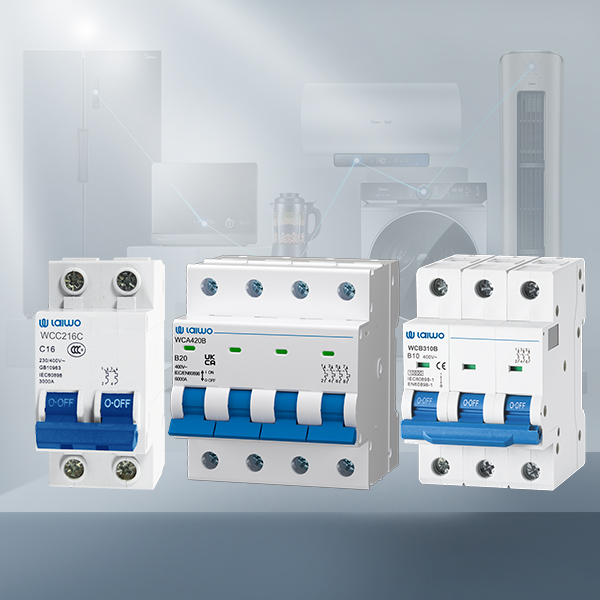
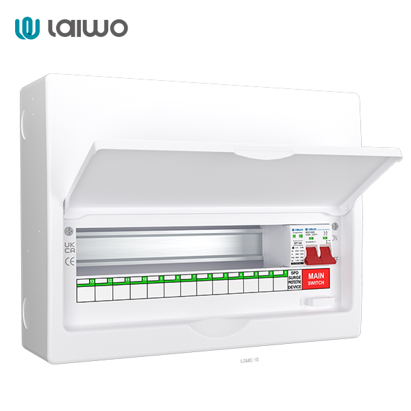
An MCB provides protection from overload and short-circuit current. In an EV charger circuit:
Typical ratings: For a domestic single‐phase 7 kW charger ≈ 32 A nominal current; for an 11 kW three-phase charger ≈ 40-45 A; for a 22 kW three‐phase charger ≈ 63 A (depending on the supply voltage and exact spec). For example, in one manufacturer’s manual a 7 kW model requires a 40 A rated breaker.
Breaker curve: The choice between B, C or D curve matters because EV chargers may exhibit inrush currents (charging electronics, onboard supplies) or multiple simultaneous chargers. A B-curve trips fast for moderation loads; a C or D curve gives more head-room for inrush and may be required in commercial installations or when adjacent loads may cause surges.
Continuous load considerations: Since the charger may run for several hours, the MCB must deal not only with fault conditions but also continuous current without nuisance tripping. As noted, some guidance suggests a device rated significantly higher than the calculated continuous current when considering adjacency of other loads in the consumer unit.
Learn More Laiwo's MCB
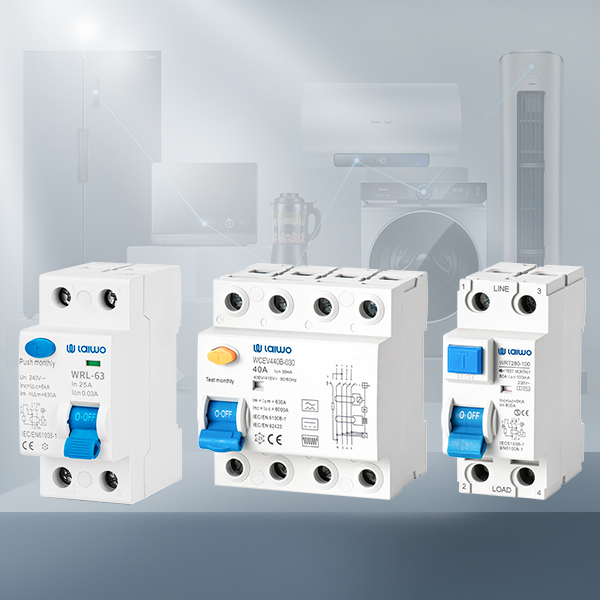
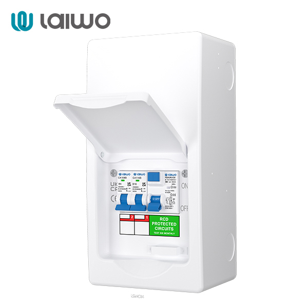
An RCD (also called RCCB) is required to protect against earth leakage (AC, pulsating DC, potentially smooth DC) and thereby protect persons and property from electric shock or fire risk due to residual current. For EV charging:
As per Regulation 722.531.3.101 of BS 7671:2018+A2:2022, “each charging point incorporating a socket-outlet or vehicle connector … is to be protected individually by an RCD of Type A, Type F or Type B and having a rated residual operating current not exceeding 30 mA. The RCD shall disconnect all live conductors.”
If the EV charging equipment does not incorporate DC fault detection (RDC-DD) then a Type B RCD must be used (it detects AC and DC residual currents). If the charger does incorporate an RDC-DD for DC faults above 6 mA then a Type A (or Type F) RCD may suffice.
Sensitivity: 30 mA is mandated (for person protection) in EV circuits unless another protective measure applies.
Must disconnect all live conductors (including neutral) – therefore single-pole RCDs are not acceptable when the neutral is live in the context of the charger circuit.
Learn More Laiwo's RCCB
.jpg)
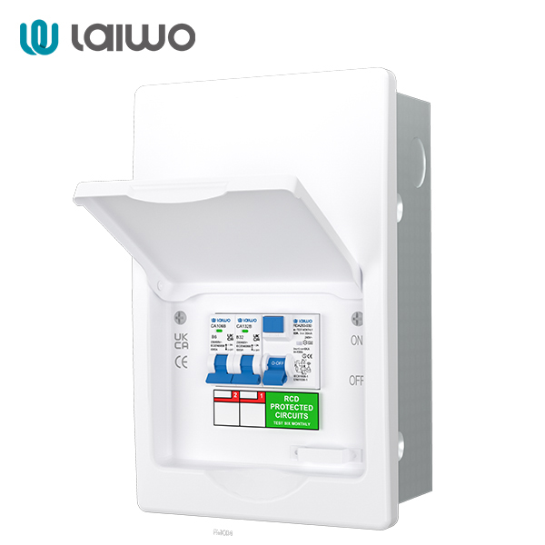
An RCBO combines the functions of an MCB and an RCD in one device. For EV charger circuits this has advantages:
Compact installation: in a dedicated EV consumer unit you can provide both over‐current/short‐circuit and earth‐leakage protection in one outgoing way.
Better fault isolation: only the EV circuit trips if a fault arises, leaving other circuits intact (especially beneficial in busier consumer boards).
Ideal for single-point residential installations or small commercial setups where the EV charger is the only major load in the distribution board.
Learn More Laiwo's RCBO
.jpg)
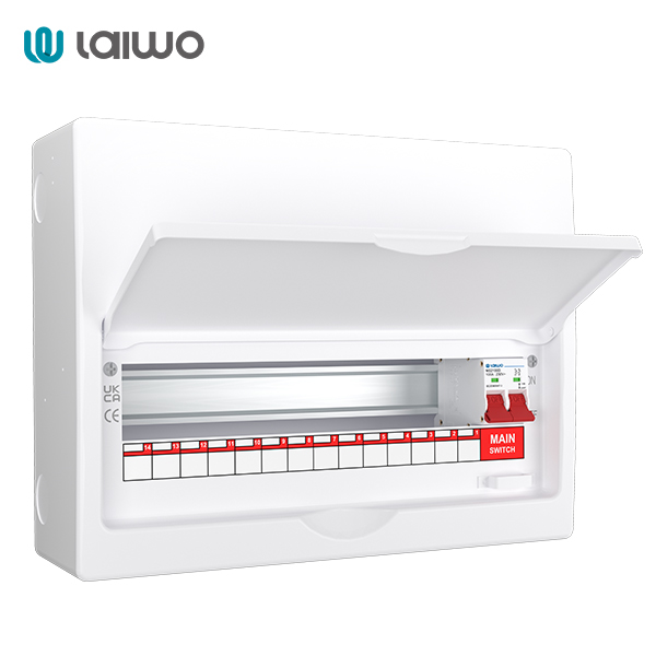
A main switch or disconnector is part of a charger distribution board so that the charger circuit can be fully isolated for maintenance, inspection or when load balancing changes require safe servicing. Key points:
The main switch should be rated appropriately (e.g., matching the breaker capacity or more) and be lockable for safety.
In EV charger distribution boards (residential or commercial) it is common to include a main switch at the head of the sub-panel, followed by MCB/RCBO outgoing ways for each charger, plus RCD/RCBO as required.
In multi-charger multi-phase systems, the main isolator supports maintenance, balancing or future expansion.
Learn More Laiow's Main Switch Disconnector
A commonly used guideline is: breaker rating ≥ charger rated current × 125 % (to allow for continuous duty). For example:
A 7 kW single-phase charger at 230 V: current ≈ 7,000 W ÷ 230 V ≈ 30.4 A → ×125% ≈ 38 A → suitable breaker 40 A (or 32 A if manufacturer allows and cable rating supports).
An 11 kW three-phase charger at 400 V (assuming balanced): current ≈ 11,000 ÷ (√3×400) ≈ 15.9 A per phase → ×125% ≈ 20 A per phase → breaker 20–25 A per phase or as specified by manufacturer (often quoted 20 A). One manufacturer’s manual: 11 kW model with 400 V/20 A breaker.
A 22 kW three-phase charger: e.g., 22,000 ÷ (√3×400) ≈ 31.8 A → ×125% ≈ 40 A per phase → breaker ≈ 40 A per phase (or as required by installation/installer).
Documented guidance (Hager EV Bitesize Guide) indicates that for a 7 kW charger the protective device may need to be 63 A (MCB/RCBO) in certain consumer-unit adjacency load/derating circumstances.
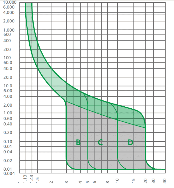
The curve of the breaker defines how quickly the breaker trips under overload/inrush conditions:
B-curve: trips relatively fast (1.13 to 1.45 × In within 1 s); suitable for general domestic resistive or light-inductive loads.
C-curve: trips slower under moderate inrush (1.45 to 2.35 × In within 1 s); suitable for circuits with some inductive/motor loads.
D-curve: trips much slower (2.8 to 5 × In within 1 s); used for heavy inrush loads (transformers, motors, heavy equipment).
For EV charger circuits:
If the charger and cable run are straightforward, and the inrush is limited, a B or C curve may be adequate.
If the charger has heavy electronics, built-in features, or is part of a multi-charger installation with simultaneous starts, a C or even D curve may be required to avoid nuisance tripping.
Always check the charger manufacturer’s specification for recommended breaker curve and coordination with RCD/RCBO.
One of the key rules for EV charger installation: the charger must have a dedicated circuit (under BS 7671 Section 722). Regulation 722.533.101 requires a new individual final circuit for each charging point.
Why dedicated?
Shared circuits risk overloading, voltage drop, thermal stress and interference between loads, leading to nuisance tripping or reduced charger performance.
For safety: leakage or fault current in one circuit should not affect unrelated circuits. Section 722 emphasises that the RCD must protect the charging point individually (i.e., not shared with other circuits).
In multi-charger installations (commercial/managed), dedicated circuits simplify load-management, fault-isolation and maintenance.
When purchasing protective devices for EV charger circuits, check the following:
Breaker rated current supports the charger’s full load (and includes margin for continuous duty, e.g., ×125%).
Breaker curve (B/C/D) selected appropriately based on charger inrush or adjacent loads.
RCD/RCBO rated residual current ≤ 30 mA for the charging point, and type (A/F/B) as required by charger manufacturer and installation earthing/fault profile.
The RCD must disconnect all live conductors (including neutral) in the circuit.
Certification: RCD must conform to BS EN 61008-1 or BS EN 61009-1 as appropriate; breaker must conform to BS EN 60898-1 or equivalent.
Manufacturer’s Declaration of Conformity for the charger and protective devices. Ensure compatibility between charger and protection device (e.g., built-in RDC-DD or not).
Future-proof capacity: Choose breaker and consumer unit with spare ways and capacity for upgrade.
Maintenance/testability: Devices should have test buttons, clear labeling, and accessible for periodic inspection.
Distribution board layout: Ensure spacing of devices, heat dissipation, and derating of adjacent continuously loaded devices (consult BS EN 61439-3 “Assumed Loading Factor” if needed).
Supplier traceability and support: Especially important in B2B supply chain; ensure supplier of breakers/RCDs can support spec, provide technical data sheets, and meet project lead-times.
Be aware of these frequent errors contractors or engineers make when specifying EV charger circuit protection:
Installing a shared RCD for the EV charger and other circuits — this contravenes the requirement for individual protection of each charging point (Regulation 722.531.3.101). Shared RCDs increase risk and make fault-finding more difficult.
Using an RCD of the wrong type (e.g., Type AC instead of A/B/F) which may be “blinded” by DC components and fail to operate.
Undersizing the breaker or relying purely on the charger specification without factoring continuous load, adjacent device derating or future expansion (e.g., specifying 32 A device for a 7 kW charger when load may justify 40 A+).
Neglecting cable sizing, voltage drop or thermal characteristics of the charger circuit — improper cable or routing can cause voltage drop, overheating or nuisance trips.
Ignoring the earthing arrangement (e.g., PME vs TT) and failing to address regulation requirements such as open PEN detection or earthing electrode separation in outdoor charger installations.
Not allowing for spare ways or planning for future upgrades (e.g., adding an extra EV charger or switching to higher power) which may force rewiring or consumer unit replacement later.
Failing to check manufacturer’s instructions: many chargers specify the type of protective device, or whether they have built-in DC residual detection (RDC-DD). If you assume incorrectly, you may end up non-compliant.
Not documenting or labeling the charger circuit properly in the consumer unit — making maintenance, fault-finding and future expansion more difficult.
For B2B buyers (electrical contractors, distributors, engineers) it is vital to source protective devices from certified manufacturers with full technical support. Consider:
Suppliers who provide full technical data sheets, application notes specific to EV charger installations.
OEM/ODM options (for sub-panels or consumer units dedicated to EV chargers) that integrate breaker/RCD/RCBO layouts with space for future chargers.
Distribution boards or consumer units specifically certified for continuous duty and EV-chargers (check manufacturer documents for “assumed loading” or EV charger compatibility).
Arrangements for spare-ways supply, labeling kits, documentation support and project-specific configuration (especially important for commercial installations).
After-sales support and documentation (for inspection and testing: e.g., EIC, EICR, consumer unit records).
Ensure that all devices carry UKCA (post-Brexit) or CE marking (if applicable) and that the manufacturer’s claims correspond with the project spec (e.g., rated current, curve, Type A/B RCD).
EV charging circuits are continuous high-current loads, so standard domestic breaker selection is often insufficient.
Follow the calculation: breaker rating ≥ charger rated current × 125% (plus check cable, voltage drop and consumer-unit adjacency).
Choose the correct breaker curve (B/C/D) to accommodate inrush and adjacent loads.
Provide individual protection for each charger circuit (MCB/RCBO + RCD) in accordance with BS 7671 Section 722.
Use the correct RCD type (Type A/F/B) with ≤ 30 mA residual current, and ensure it disconnects all live conductors.
Consider earthing/fault loop, cable installation method, derating, wiring method, load sharing and future expansion from the outset.
Work with certified devices and suppliers — check declarations, compliance with relevant standards and project documentation.
If the charger is low power (e.g., a portable charger or <3.7 kW via standard socket) the protection might in effect be similar to a standard socket circuit, but care must still be taken.
For dedicated installed chargers of 7 kW and above (single-phase or three-phase), you are in EV-charger territory and you must treat the circuit as an EV-specific installation: dedicated final circuit, correct RCD type, continuous duty device sizing, etc.
In commercial/multi-charger installations, multiple chargers sharing a supply or distribution board require more sophisticated protection/selectivity, load-balancing, and possibly higher rated devices or specialised panels.
Specify consumer units/distribution boards with spare ways and sufficient busbar and cable capacity for adding future chargers (or upgrading to higher power).
Consider using RCBOs for outgoing ways so that each circuit is individually isolated and maintainable.
Consider integration of load-management communications (smart metering, load-sharing, utility signalling). Recent guidance emphasises this for installations after 2022.
Think ahead about cable routing, future charger positioning, and flexibility (for example dual chargers on one garage wall, or multiple bays in commercial sites).
Document the installation: labeling, circuit diagrams, capacity statements and future-upgrade notes will support maintenance, compliance and client satisfaction.
What size breaker do I need for a 7 kW EV charger?
Typically around 30–32 A nominal current for 7 kW at 230 V single-phase (7,000 ÷ 230 ≈30.4 A). Applying the 125% continuous load factor gives about 38 A, so a 40 A breaker is often chosen. Some contractors still use 32 A if the cable and installation allow and manufacturer permits.
Can I use a standard MCB for an EV charger circuit?
Yes—but only if it’s sized correctly for continuous load, of the correct curve type, and the RCD/RCBO protection is correctly specified. If you simply use a standard lighting box MCB without checking these factors, you risk nuisance trips, thermal issues or non-compliance.
Do I need an RCCB or RCBO for an EV charger?
Yes. The circuit must be protected by an RCD (≤30 mA residual current) of the correct type (A/F/B) and disconnect all live conductors. An RCBO is often preferred because it combines over-current and residual-current protection in one device, which simplifies the board and improves fault isolation.
Why do RCDs trip at 30 mA?
30 mA is the common threshold for person protection (electric shock) in fixed installations. The regulation for EV charging (Section 722) requires the RCD to have rated residual operating current not exceeding 30 mA.
What’s the difference between 30 mA and 100 mA RCDs?
A 30 mA device provides protection for persons (shock risk) and is required in sensitive circuits like EV chargers. A 100 mA RCD may be used for fire-risk protection in certain circuits, but it is not acceptable for the charging point circuit under BS 7671 Section 722, which specifies ≤30 mA.
Why does the breaker curve matter for EV chargers?
Because EV chargers may have inrush currents (especially at start) or other dynamic behaviour, and they run for long periods (continuous load). The breaker curve determines how fast the breaker trips under overload/inrush. If you pick a curve too aggressive (e.g., B-curve) and there is inrush, you risk nuisance trips. If you pick a too slow curve (e.g., D) you may compromise protection. Selecting the correct curve ensures reliable charging and protection.
Learn More: