Next: What is the difference between a circuit breaker and a circuit protector?


Fuses serve as indispensable electrical safety devices, playing a crucial role in protecting electrical circuits from the detrimental effects of overcurrent conditions. These devices are specifically designed to interrupt the flow of electrical current when it exceeds a predetermined safe level, thereby preventing damage to equipment and reducing the risk of electrical fires. In the realm of electrical schematics and diagrams, standardized graphical symbols for fuses are paramount. These symbols facilitate effective communication among engineers, electricians, and technicians, transcending geographical and industrial boundaries. The establishment and maintenance of these standards are primarily the responsibility of international and national standardization bodies, including the International Electrotechnical Commission (IEC), the Institute of Electrical and Electronics Engineers (IEEE), and the American National Standards Institute (ANSI). The existence of these distinct standards underscores the necessity for a clear understanding of the specific standard being utilized in any given schematic to ensure accurate interpretation. Over time, fuse symbols have undergone an evolution, with standardization becoming increasingly important for promoting clarity and preventing confusion in the design and analysis of electrical circuits.
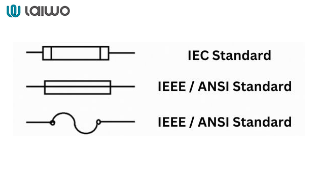
The fundamental symbols employed to represent a basic fuse in electrical diagrams exhibit variations depending on whether the schematic adheres to IEC or IEEE/ANSI standards.
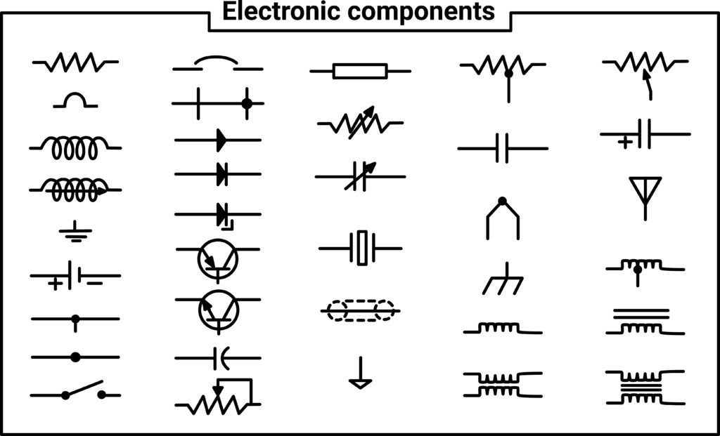
Under IEC standards, the generic fuse symbol is typically depicted as a filled rectangle with a line passing through its center. The simplicity of this rectangular shape, however, means that it might also represent other components like inductors under certain international conventions. Furthermore, as noted in , a rectangle could potentially symbolize a resistor or a connector. This inherent ambiguity underscores the importance of carefully examining the context of the diagram and referring to any accompanying legends to ensure correct identification.
In contrast, the IEEE/ANSI generic fuse symbol is commonly represented in one of two ways: either as a zig-zag line enclosed within a rectangle or as an open rectangle with a line passing through it. This variation within the IEEE/ANSI standard suggests that the specific representation might be influenced by different versions of the standard or the particular application for which the schematic is intended. Regardless of the specific form, both symbols serve the same fundamental purpose of indicating overcurrent protection.
Learn More: What is the difference between a fuse and a MCB?
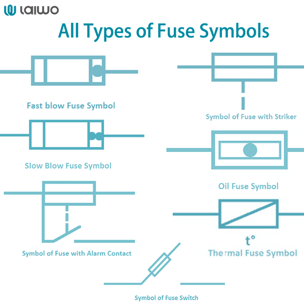
Beyond the generic representations, electrical systems often incorporate specialized types of fuses designed for specific protection characteristics. These specialized fuses are represented by distinct symbols that convey their unique functionalities.
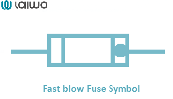
The fast blow fuse symbol is typically depicted with a straight line or a slightly angled line traversing the generic fuse symbol. This symbol signifies the fuse's primary characteristic of providing instantaneous protection against overcurrents, making it ideal for safeguarding sensitive electronic components that are vulnerable to even brief periods of excessive current.
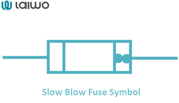
Conversely, the slow blow fuse symbol is often represented with a curved or S-shaped line passing through the generic fuse symbol. This distinctive line indicates the fuse's ability to tolerate momentary surges of high current, such as those that occur when motors are starting up. This characteristic renders slow blow fuses particularly suitable for applications involving inductive loads that exhibit high inrush currents.
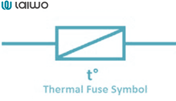
The thermal fuse symbol is designed to indicate a temperature-sensitive switch. It often incorporates a representation of a bimetallic strip or another temperature-sensing element within or adjacent to the generic fuse symbol. Unlike standard fuses that react to current overload, thermal fuses operate based on temperature, providing crucial protection against overheating in appliances where excessive heat can lead to damage or fire.
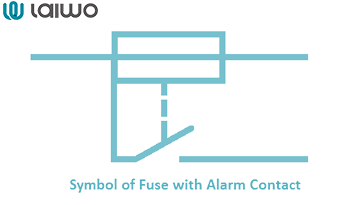
A fuse with alarm contact symbol includes an additional contact symbol, typically a small circle or extension, connected to the main fuse symbol. This signifies that the fuse has an integrated alarm circuit that activates when the fuse blows, providing a visual or audible indication of the fault. Such fuses are particularly useful in systems where the early detection of a fault is critical for minimizing downtime or preventing further damage.
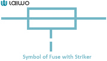
The striker fuse symbol is characterized by a small arrow or a pin-like extension on the fuse symbol. This represents a striker pin that is released when the fuse blows, providing an immediate visual indication of the fuse's condition. This visual cue simplifies the process of identifying blown fuses, especially in panels containing multiple fuses.
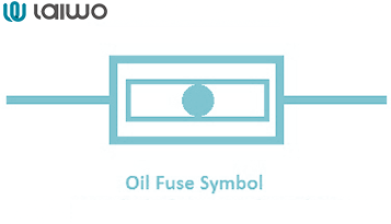
For high-current applications, oil type fuses are often employed. Their symbols commonly include a representation of a fluid enclosure, such as a wavy line or a specific shape surrounding the fuse symbol. This denotes that the fuse is immersed in oil, which provides a cooling effect and enhances the fuse's breaking capacity, making it suitable for power distribution systems.
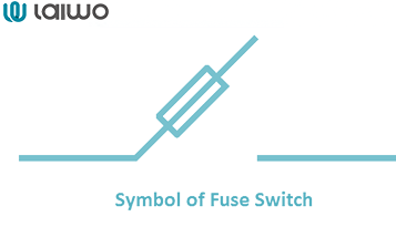
A fuse switch symbol integrates the symbols of both a fuse and a switch. This combination indicates a device that offers both overcurrent protection and the ability to manually disconnect the circuit , providing a convenient solution for circuit protection and control.
The fuse switch disconnector symbol represents a device that combines the functionalities of a fuse, a switch, and a disconnector or isolator. These devices allow for manual switching, provide overcurrent protection, and enable the complete isolation of the circuit, which is essential for ensuring safety during maintenance, particularly in industrial and commercial settings with high current levels.
While not a fuse itself, the thermal overcurrent symbol is related to circuit protection and is often used in conjunction with fuses. It typically depicts a specific symbol indicating a thermally activated contact. These devices provide protection against sustained overcurrents that might not immediately cause a fuse to blow but could lead to the overheating of components, such as motor windings.
Lastly, some specialized symbols represent protection resistors that function similarly to fuses by blowing open when a current limit is exceeded. These components offer a combined approach of limiting current flow up to a certain point and then interrupting the circuit entirely if a higher threshold is reached.
Learn More: Miniature Circuit Breaker Symbols in Electrical Diagrams
The selection and representation of fuse symbols in electrical diagrams can vary significantly depending on the specific application and the industry in question.
In residential and commercial systems, basic fuse symbols are often sufficient to represent the standard overcurrent protection found in circuit panels and distribution boards. The emphasis in these applications is on simplicity and ease of understanding for both homeowners and electricians who need to quickly identify the protective elements within the electrical system.
Industrial systems, on the other hand, frequently employ a more extensive range of fuse symbols. This includes symbols for heavy-duty fuses, fuse switches, and fuse disconnectors, which are necessary to address the complexities and high current levels inherent in industrial circuits. The presence of large machinery and intricate electrical distribution networks in industrial environments necessitates more sophisticated protection and control mechanisms.
Automotive systems utilize specific types of fuses, such as blade fuses and cartridge fuses, each with its corresponding symbol in wiring diagrams. While automotive fuses often feature color-coding related to their amperage rating, this is typically indicated through labels or fuse specification charts rather than being directly incorporated into the schematic symbol.
High voltage systems rely on specialized fuses like high-rupturing capacity (HRC) fuses and oil-immersed fuses. The symbols for these fuses may include specific indicators to denote their high breaking capacity or the presence of oil immersion. Safety and the ability to interrupt substantial fault currents are paramount in these systems.
The marine industry employs fuses that are specifically designed to withstand the harsh marine environment, often emphasizing corrosion resistance. However, the schematic symbols used in marine applications generally align with standard electrical conventions, without significant deviations.
In the aerospace industry, fuses are subject to extremely stringent performance and reliability requirements due to the critical nature of their applications. The symbols used in aerospace electrical diagrams typically adhere to industry-specific standards, which may share similarities with military standards.
Medical equipment utilizes fuses that must comply with rigorous safety standards, such as IEC 60601. The symbols used generally follow IEC conventions, often accompanied by additional markings or documentation to specify compliance with these medical safety standards.
The basic fuse symbol can be augmented with additional graphical elements to represent specific components or features of the fuse. For instance, alarm contacts are typically indicated by an additional contact symbol extending from the main fuse symbol, signifying the presence of an integrated alarm circuit. A striker pin, which provides a visual indication when the fuse has blown, is often represented by a small arrow or pin-like extension on the fuse symbol. For oil type fuses, a wavy line or a specific shape surrounding the fuse symbol is commonly used to denote the oil enclosure. When a fuse is integrated with a switch, the symbol will be a combination of the standard fuse symbol and a switch symbol. In applications involving multiple linked fuses, such as three-phase systems, dotted lines connecting the individual fuse symbols are used to indicate mechanical linkage and simultaneous operation. Recognizing these additional symbolic elements is essential for a comprehensive understanding of the fuse's specific role and functionality within the electrical system.
Accurately understanding and interpreting fuse symbols in electrical systems is of paramount importance for ensuring safety, facilitating effective design, enabling efficient maintenance, and supporting accurate troubleshooting. Given the variations that exist between different standardization bodies like the IEC and IEEE/ANSI, as well as across various applications and industries, it is crucial to always refer to the relevant standards and any accompanying schematic legends for correct interpretation. The ongoing relevance of fuses as critical safety components in electrical systems underscores the continuous necessity for professionals and students in electrical engineering and related fields to possess a thorough understanding of their symbolic representations. As technology evolves and electrical systems become more complex, a solid grasp of these fundamental symbols remains essential for ensuring the reliable and safe operation of electrical installations worldwide.

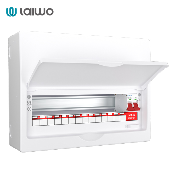
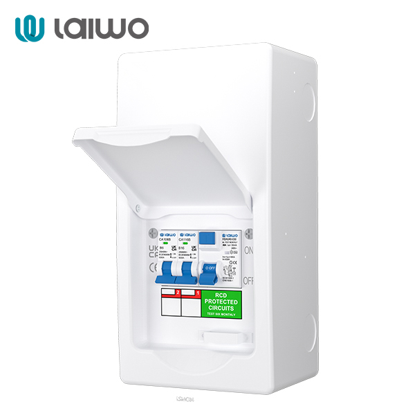
When investing in electrical protection devices such as MCBs, RCCBs or RCBOs, make sure that you always get help from a reliable manufacturer/supplier such as laiwo. laiwo electrical is a one-stop solution for all your electrical needs including surge protectors, distribution boxes, earth leakage protection devices and switched sockets. If you have additional questions or need assistance, please feel free to contact the customer service team. Give us a call and we'll have a team of professionals answer your questions!
Source:
All Types of Fuse Symbols and Diagrams
Fuse, Circuit Breaker and Electrical Protection Symbols - Pinterest